Product Description
Disc Couplings Torsionally Rigid Double Packs with Spacer Diaphragm Coupling
Product Description
1. Applies to flexibly drive shaft, allowing a more significant axial radial displacement and displacement.
2. It Has a simple structure and easy maintenance.
3. Disassembly is easy.
4. low noise.
5. Transmission efficiency loss, long useful working life.
Product Photos
Product Parameters
| Size | Torque Tn/N.m |
Speed (rpm) |
Weight/kg | Moment of inertia g cm’ |
Main size/mm | Allowable compensation | |||||||
| d | D | A | B | L | C | Axial | Angular | Radial | |||||
| 00 | 9.8 | 20000 | 0.23 | 3 | 3-20 | 57 | 4.9 | 20 | 100 | 60 | ±1.6 | 2° | 0.5 |
| 01 | 33 | 20000 | 1.2 | 8 | 5-22 | 68 | 6.1 | 26 | 141 | 89 | ±1.6 | 2° | 0.5 |
| 02 | 90 | 20000 | 1.9 | 24 | 6-32 | 81 | 6.6 | 26 | 141 | 89 | ±1.6 | 2° | 0.5 |
| 03 | 173 | 18000 | 2.9 | 48 | 8-35 | 93 | 8.4 | 29 | 160 | 102 | ±2.4 | 2° | 0.6 |
| 04 | 245 | 15000 | 4.7 | 80 | 10-42 | 104 | 11.2 | 34 | 195 | 127 | ±2.8 | 2° | 0.7 |
| 05 | 420 | 13000 | 7.1 | 224 | 15-50 | 126 | 11.7 | 42 | 211 | 127 | ±3.2 | 1°30″ | 0.7 |
| 06 | 772 | 12000 | 10.8 | 400 | 20-60 | 143 | 11.7 | 48 | 223 | 127 | ±3.6 | 1°30″ | 0.8 |
| 07 | 1270 | 10000 | 16.3 | 1080 | 25-75 | 168 | 16.8 | 58 | 243 | 127 | ±4.0 | 1°30″ | 0.8 |
| 08 | 2080 | 10000 | 24.7 | 2080 | 30-82 | 194 | 17.0 | 64 | 268 | 140 | ±4.4 | 1°30″ | 0.9 |
| 09 | 3328 | 9000 | 32.5 | 3520 | 30-95 | 214 | 21.6 | 77 | 306 | 152 | ±4.8 | 1°30″ | 0.9 |
| 10 | 4900 | 8000 | 50 | 7200 | 10-108 | 246 | 23.9 | 89 | 356 | 178 | ±5.2 | 1°30″ | 1.0 |
| 11 | 6368 | 6300 | 75 | 12800 | 52-118 | 276 | 27.2 | 102 | 382 | 178 | ±5.6 | 1°30″ | 1.2 |
| 12 | 8900 | 6300 | 72.2 | 18000 | 60-110 | 276 | 17.5 | 128 | 409 | 153 | ±3.6 | 1″ | 1.2 |
| 13 | 15280 | 5000 | 120 | 37000 | 60-135 | 308 | 19.0 | 160 | 492 | 172 | ±4.0 | 1″ | 1.2 |
| 14 | 25410 | 4700 | 175 | 68000 | 60-155 | 346 | 21.5 | 182 | 554 | 190 | ±4.0 | 1″ | 1.2 |
| 15 | 37130 | 4300 | 234 | 108000 | 60-165 | 375 | 24.0 | 198 | 620 | 224 | ±4.0 | 1″ | 1.3 |
| 16 | 47120 | 3900 | 306 | 167000 | 70-180 | 410 | 29.5 | 214 | 682 | 254 | ±4.4 | 1″ | 1.3 |
| 17 | 57000 | 3500 | 369 | 250000 | 70-190 | 445 | 29.5 | 225 | 720 | 270 | ±4.4 | 1″ | 1.4 |
| 18 | 63186 | 3500 | 448 | 311000 | 80-205 | 470 | 31.0 | 248 | 770 | 274 | ±4.8 | 1″ | 1.5 |
| 19 | 82590 | 3200 | 596 | 480000 | 90-230 | 512 | 32.0 | 278 | 843 | 287 | ±4.8 | 1″ | 1.6 |
| 20 | 157100 | 2800 | 763 | 747000 | 90-255 | 556 | 32.5 | 305 | 902 | 292 | ±5.2 | 1″ | 1.8 |
| 21 | 126070 | 2450 | 919 | 1016000 | 100-265 | 588 | 34.0 | 318 | 948 | 312 | ±5.4 | 1″ | 1.8 |
| 22 | 146350 | 2150 | 1068 | 1386000 | 100-275 | 630 | 34.0 | 332 | 1008 | 344 | ±5.6 | 1″ | 2.0 |
| 23 | 173830 | 2000 | 1235 | 1784000 | 100-290 | 655 | 35.5 | 348 | 1052 | 356 | ±6.0 | 1″ | 2.0 |
Related Products
Company Profile
FAQ
Q: Can you make the coupling with customization?
A: Yes, we can customize per your request.
Q: Do you provide samples?
A: Yes. The sample is available for testing.
Q: What is your MOQ?
A: It is 10pcs for the beginning of our business.
Q: What’s your lead time?
A: Standard products need 5-30days, a bit longer for customized products.
Q: Do you provide technical support?
A: Yes. Our company has a design and development team, and we can provide technical support if you
need.
Q: How to ship to us?
A: It is available by air, sea, or by train.
Q: How to pay the money?
A: T/T and L/C are preferred, with different currencies, including USD, EUR, RMB, etc.
Q: How can I know if the product is suitable for me?
A: >1ST confirm drawing and specification >2nd test sample >3rd start mass production.
Q: Can I come to your company to visit?
A: Yes, you are welcome to visit us at any time.
Q: How shall we contact you?
A: You can send an inquiry directly, and we will respond within 24 hours. /* January 22, 2571 19:08:37 */!function(){function s(e,r){var a,o={};try{e&&e.split(“,”).forEach(function(e,t){e&&(a=e.match(/(.*?):(.*)$/))&&1
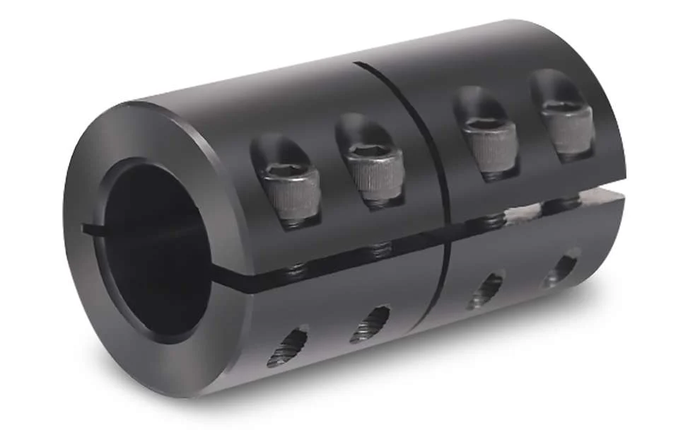
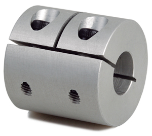
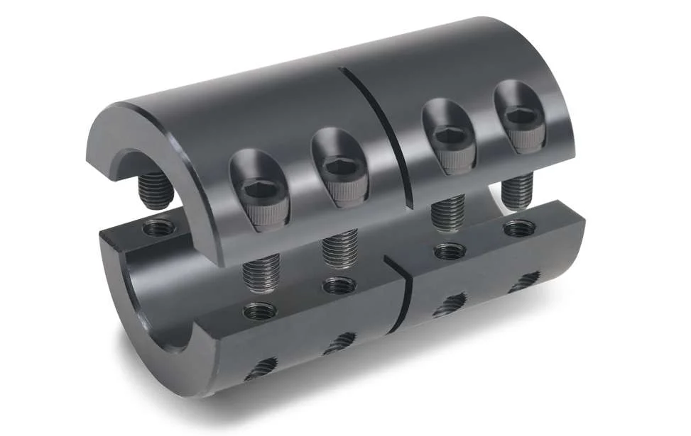
Can Rigid Couplings Handle Misalignment Between Shafts?
Rigid couplings are not designed to handle misalignment between shafts. Unlike flexible couplings that can accommodate slight misalignment through their bending or elastic properties, rigid couplings are intended to provide a fixed and immovable connection between two shafts. As a result, any misalignment between the shafts can lead to increased stress and uneven loading on connected components.
It is essential to ensure precise alignment when using rigid couplings to avoid premature wear and failure of the system. The shafts must be perfectly aligned in both the axial and angular directions before installing the rigid coupling. Proper alignment helps distribute the load evenly and reduces stress concentration on specific areas, such as bearings and keyways.
If a system requires some level of misalignment compensation due to factors like thermal expansion or slight shaft deflection, a flexible coupling should be considered instead. Flexible couplings can tolerate small degrees of angular and axial misalignment while still transmitting torque efficiently and protecting the connected equipment from excessive stress and wear.
In summary, rigid couplings are best suited for applications where precise shaft alignment can be achieved and maintained, while flexible couplings are more appropriate for systems with potential misalignment or other dynamic factors that require some degree of flexibility.
What Role Does a Rigid Coupling Play in Reducing Downtime and Maintenance Costs?
A rigid coupling can play a significant role in reducing downtime and maintenance costs in mechanical systems by providing a robust and reliable connection between two shafts. Here are the key factors that contribute to this:
1. Durability and Longevity: Rigid couplings are typically made from high-quality materials such as steel or stainless steel, which offer excellent durability and resistance to wear. As a result, they have a longer service life compared to some other types of couplings that may require frequent replacements due to wear and fatigue.
2. Elimination of Wear-Prone Components: Unlike flexible couplings that include moving parts or elements designed to accommodate misalignment, rigid couplings do not have any wear-prone components. This absence of moving parts means there are fewer components that can fail, reducing the need for regular maintenance and replacement.
3. Minimization of Misalignment-Related Issues: Rigid couplings require precise shaft alignment during installation. When installed correctly, they help minimize misalignment-related issues such as vibration, noise, and premature bearing failure. Proper alignment also reduces the risk of unexpected breakdowns and maintenance requirements.
4. Increased System Efficiency: The rigid connection provided by a rigid coupling ensures efficient power transmission between the two shafts. There is minimal power loss due to flexing or bending, leading to better overall system efficiency. This efficiency can result in reduced energy consumption and operating costs.
5. Low Maintenance Requirements: Rigid couplings generally require minimal maintenance compared to some other coupling types. Once properly installed and aligned, they can operate for extended periods without needing frequent inspection or adjustment.
6. Reduced Downtime: The robust and reliable nature of rigid couplings means that they are less likely to fail unexpectedly. This increased reliability helps reduce unscheduled downtime, allowing the mechanical system to operate smoothly and consistently.
7. Cost-Effective Solution: While rigid couplings may have a higher upfront cost than some other coupling types, their long-term durability and low maintenance requirements make them a cost-effective solution over the life cycle of the equipment.
In conclusion, a rigid coupling’s ability to provide a durable and dependable connection, along with its low maintenance requirements and efficient power transmission, contributes significantly to reducing downtime and maintenance costs in mechanical systems.
Advantages of Using Rigid Couplings in Mechanical Systems:
Rigid couplings offer several advantages when used in mechanical systems. These advantages make them a preferred choice in certain applications where precise alignment and high torque transmission are essential. Here are the key advantages of using rigid couplings:
- 1. High Torque Transmission: Rigid couplings are designed to handle high torque and power transmission without any loss due to flexibility. They provide a direct and solid connection between shafts, allowing for efficient transfer of rotational motion.
- 2. Precise Alignment: Rigid couplings maintain precise alignment between connected shafts. When installed correctly, they ensure that the two shafts are perfectly aligned, which is crucial for applications where accurate positioning and synchronization are required.
- 3. Synchronous Rotation: The rigid connection provided by these couplings enables synchronous rotation of the connected shafts. This is particularly important in applications where components must move in precise coordination with each other.
- 4. Simple Design: Rigid couplings have a straightforward design with minimal moving parts. This simplicity makes them easy to install and maintain, reducing the chances of mechanical failure.
- 5. Cost-Effective: Compared to some other coupling types, rigid couplings are generally more cost-effective. Their simple design and robust construction contribute to their affordability.
- 6. High Strength and Durability: Rigid couplings are typically made from strong and durable materials such as steel, stainless steel, or aluminum. These materials can withstand heavy loads and provide long-lasting performance in demanding applications.
Rigid couplings are commonly used in various industries and applications, including high-precision machinery, robotics, automation systems, precision motion control, and machine tools. They are especially beneficial in scenarios where misalignment needs to be minimized or avoided altogether.
It’s important to note that while rigid couplings offer these advantages, they are not suitable for applications where shaft misalignment or shock absorption is required. In such cases, flexible couplings or other specialized coupling types may be more appropriate.
editor by CX 2024-04-17


